Page 1 of 2
Bodywork dimensions
Posted: Sat Sep 05, 2020 11:06 am
by don58van
Hi fellow DIY restorers
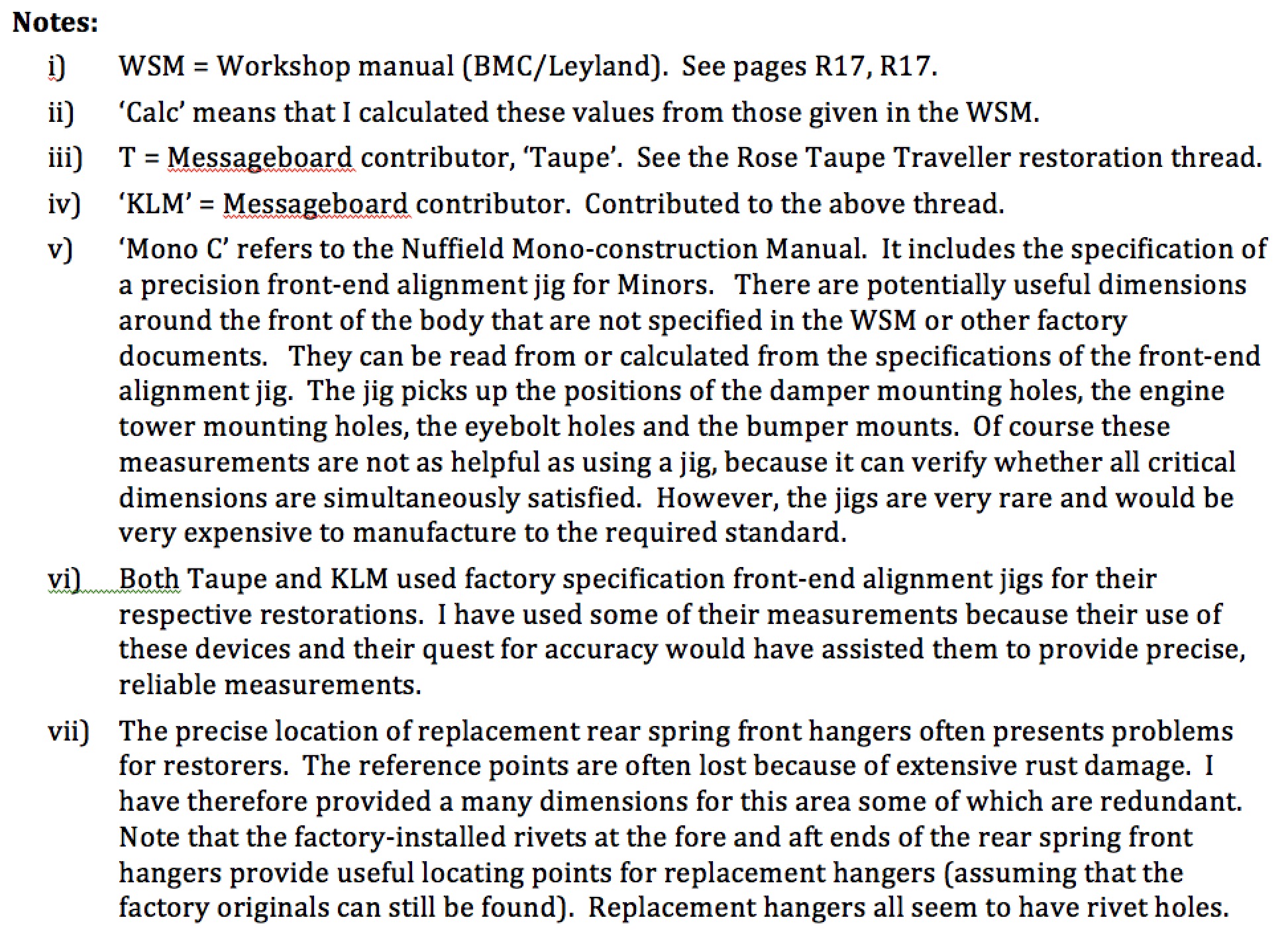
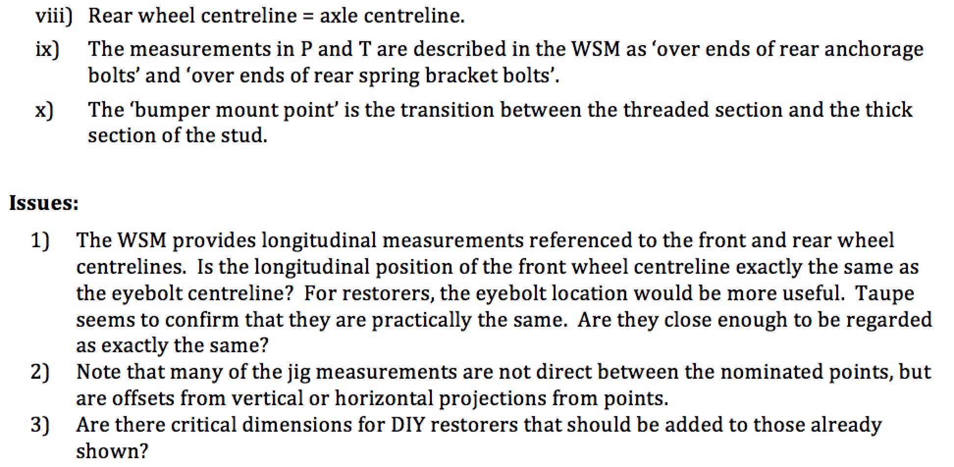
As far as I know, Minor body measurements that restorers refer to are scattered among a few factory-issued documents and on message-boards where DIY restorers share information. I am not aware of any document that brings the key information together.
Recently, I restarted work on such a document that I started many years ago. I thought that this would be useful for my own restorations (I have a couple in slow progress) and might be so for other DIY restorers.
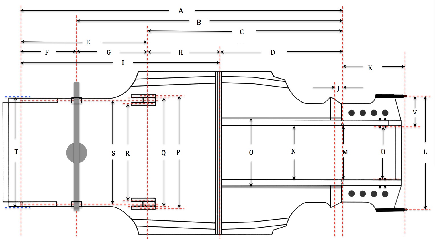
I have attached a
draft, below.
I have used a few different sources, with an emphasis on showing measurements are accurate and hopefully useful for restoration work.
I hope my arithmetic is OK because there were a lot of unit conversions and calculations involving fractions.
It would be good if others could validate my figures.
I invite your input.
Not to scale.
- DimPic11.jpg (168.36 KiB) Viewed 7610 times
- Dim1.jpg (663.94 KiB) Viewed 7610 times
- Dim2.jpg (566.83 KiB) Viewed 7610 times
- Dim3.jpg (488.56 KiB) Viewed 7610 times
Notes to follow...
Re: Bodywork dimensions
Posted: Sat Sep 05, 2020 11:09 am
by don58van
- Dim4.jpg (880.52 KiB) Viewed 7610 times
- Dim5.jpg (446.15 KiB) Viewed 7610 times
Stay well
Don
Re: Bodywork dimensions
Posted: Mon Sep 07, 2020 12:57 pm
by taupe
WOW Don you have been busy!
Taupe
Re: Bodywork dimensions
Posted: Mon Sep 07, 2020 1:05 pm
by Murrayminor
What an excellent idea, I can see this being the go to reference for years to come.
I will print a set off for my garage wall.
Well done and thank you.
Re: Bodywork dimensions
Posted: Tue Nov 10, 2020 10:02 pm
by alloriginal1owner
don58van wrote: ↑Sat Sep 05, 2020 11:06 am
I invite your input.
What a great work, thank you!
I would like to know the correct distance between the holes (center) for the rear bumper mounting studs in the boot aperture panel.
https://www.morrisminorspares.com/body- ... de-p828568 This part from ESM doesn't really fit unfortunately.
Thanks for help!
Frank
Re: Bodywork dimensions
Posted: Sun Nov 15, 2020 7:54 pm
by don58van
Hi alloriginal1owner
I cannot recall seeing a factory measurement for the rear bumper studs or for the corresponding holes in the rear panel. The best I could do is measure my 1000s (2 of them -- 1960 and 1970) which have not been 'molested'. Perhaps others could join in and give a measurement.
Regards
Don
Re: Bodywork dimensions
Posted: Mon Nov 16, 2020 9:10 pm
by alloriginal1owner
don58van wrote: ↑Sun Nov 15, 2020 7:54 pm
Perhaps others could join in and give a measurement.
Hi Don,
A member of the German club measured 890 mm plus/minus 5 mm from center to center of the holes. My welding mate and I will try and hope. I can post a photo of that very much modified spare part when it's ready, if you want.
Thanks
Frank
Re: Bodywork dimensions
Posted: Tue Nov 17, 2020 11:03 pm
by don58van
Hi Frank
I measured mine as best I could--bearing in mind that the bumper is fitted so I cannot directly access the holes in the panel (the rubber seals on the outside cover the holes). The best I could do is measure the between the centrelines of the mounting studs, directly adjacent to the panel (both inside and outside).
Having said all that I get the same result as your German friend -- 890 plus or minus a couple of mm.
I hope this helps.
Don
Re: Bodywork dimensions
Posted: Wed Nov 18, 2020 9:56 am
by alloriginal1owner
Thanks, Don!
Re: Bodywork dimensions
Posted: Tue Dec 01, 2020 12:00 am
by klm
Hi Don,
Excellent work. I will review the information provided on this post and get back soon.
Thanks for your effort !!
Kith
Re: Bodywork dimensions
Posted: Tue Jan 12, 2021 3:00 pm
by nslocomotives2
don this is awesome thankyou, i need these dimensions..
Re: Bodywork dimensions
Posted: Mon Jan 18, 2021 11:13 pm
by Nourish
DOH! I know now that my floor cross member is in the wrong place and that means that the one chassis leg fitted is out also!!!!!!
With the body shell on 3 axle stands I've levelled the two bump stops on the rear wheel arches and jacked up on the one chassis leg to level up on the inner box sills.
Now I find that the one chassis leg fitted is not at right angles to the front shock cross member - should it be?
Now then - I've got to search on how to remove a perfectly good cross member from a perfectly good floor..............
Re: Bodywork dimensions
Posted: Tue Jan 19, 2021 12:57 am
by don58van
Hi Nourish
STOP -- Don't start ripping everything out until you have confirmed the dimensions in the above chart. They should be regarded as tentative until the calculated dimensions in particular have been confirmed by others or you have double checked them yourself. Of course, even though the dimensions provided by BMC sometimes go down to several figures behind the decimal point, in practice a some tolerance would be acceptable.
Don
Re: Bodywork dimensions
Posted: Tue Jan 19, 2021 11:09 pm
by Nourish
Nah, the measurement from the front shock mount to the floor cross member is different on one side to the other.
Looking to perhaps make up a Jig - I found the dimensions, looking for the material but I can't believe the cost of mild steel.
Re: Bodywork dimensions
Posted: Sun Feb 28, 2021 11:50 am
by Nourish
Hi Don . I've made up a jig as in the drawing below
2085680672_Alignmentjig.png.57eb766d0b3f6b52991757547458783f.png
If we compare dimension K to this drawing I see we have a difference in values.
The jig I made does sit forward 1/4" to the rear of the thread on the one bumper iron that I have
Cheers
Martin
Re: Bodywork dimensions
Posted: Sun Feb 28, 2021 11:50 am
by Nourish
Hi Don . I've made up a jig as in the drawing below
- 2085680672_Alignmentjig.png.57eb766d0b3f6b52991757547458783f.png (1002.23 KiB) Viewed 6233 times
If we compare dimension K to this drawing I see we have a difference in values.
The jig I made does sit forward 1/4" to the rear of the thread on the one bumper iron that I have
Cheers
Martin
Re: Bodywork dimensions
Posted: Mon Mar 01, 2021 1:55 am
by don58van
Martin
Congratulations on building this complex device.
Thank you for the feedback. I will review my calculations for dimension K.
Regards
Don
Re: Bodywork dimensions
Posted: Thu Mar 04, 2021 9:37 am
by don58van
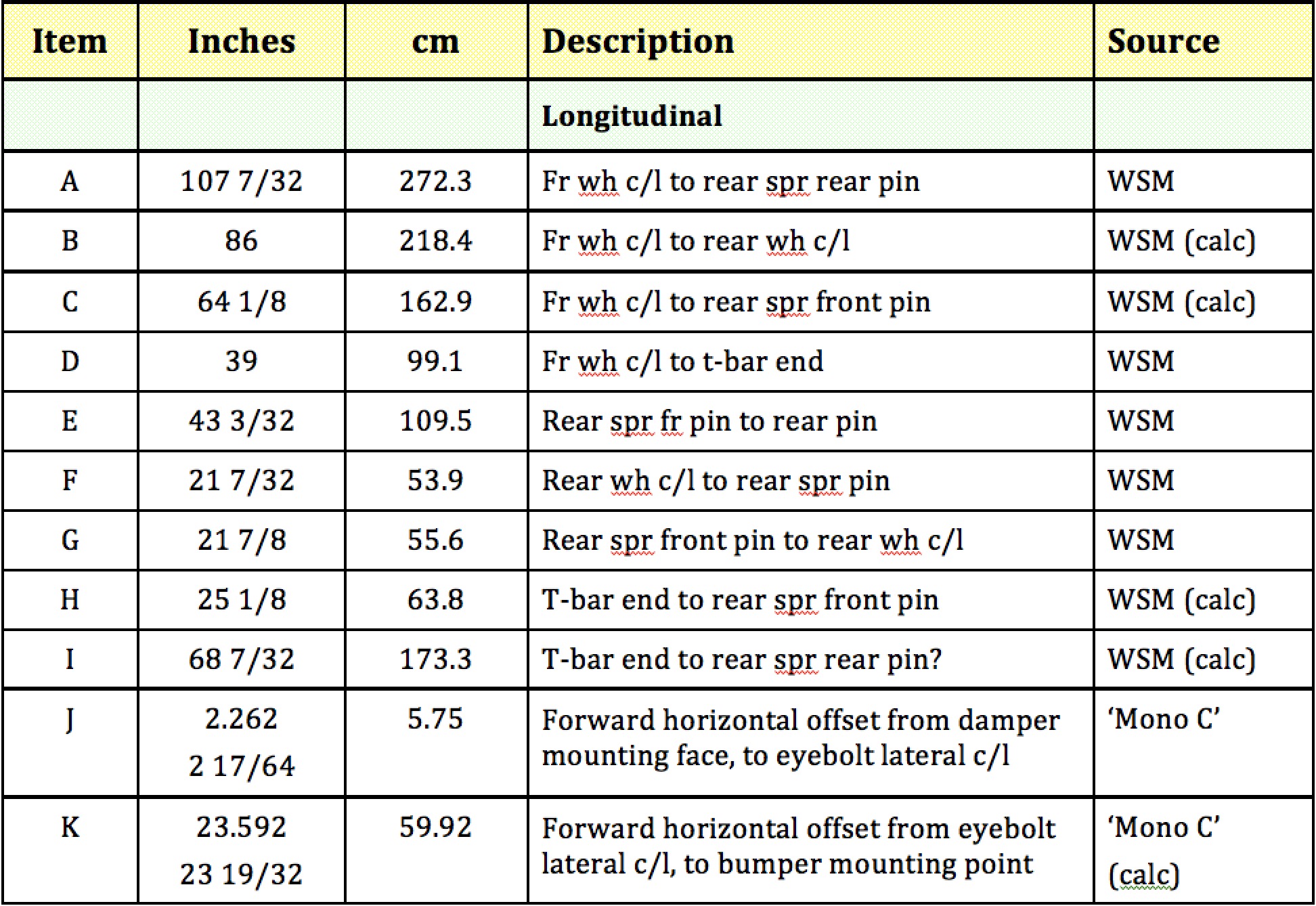
I have checked dimension K as shown in the diagram and table at the beginning of this thread.
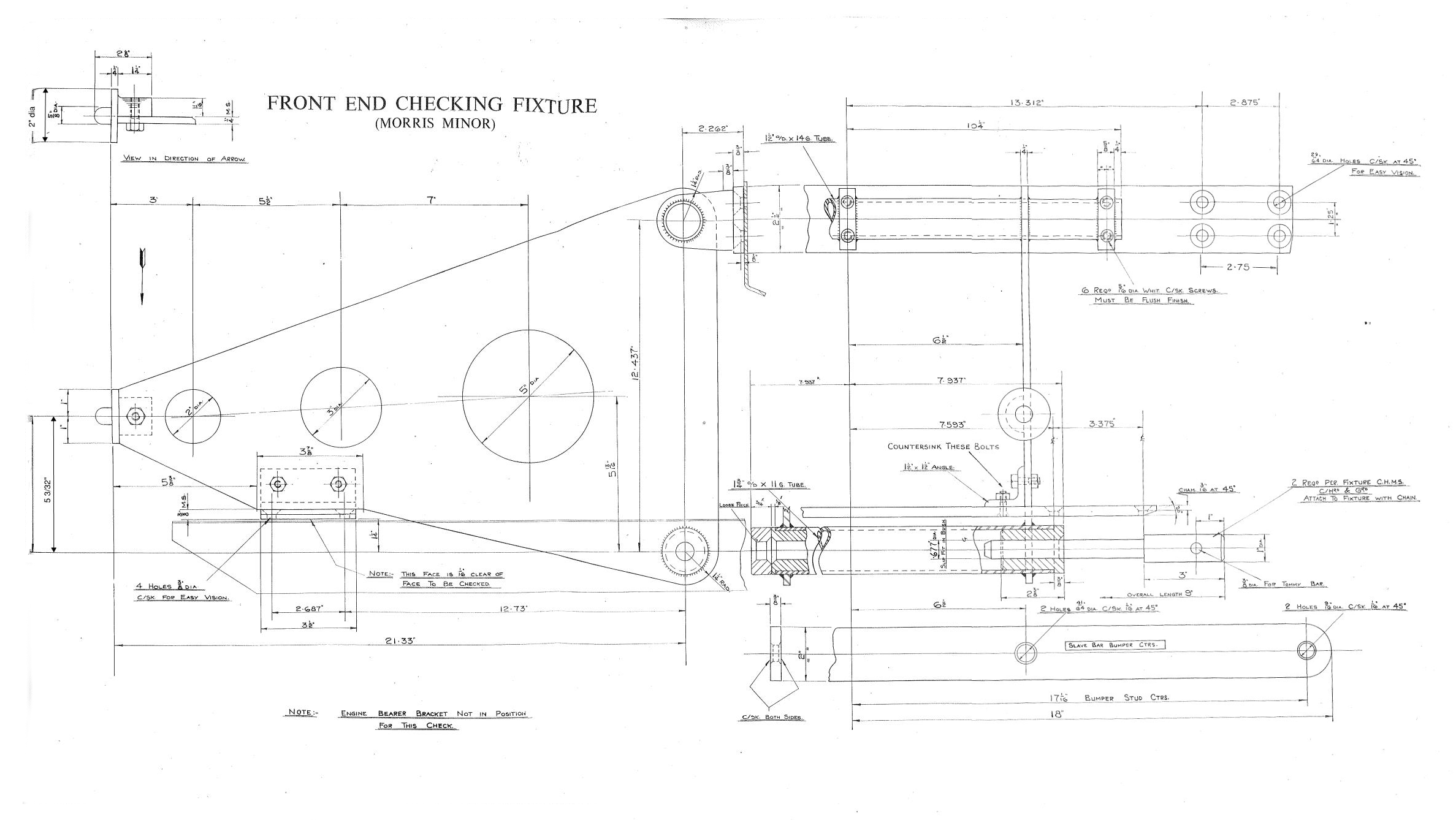
And yes, Martin you are correct. The correct value for K is 21.33in, which can be read directly from the alignment jig diagram. The clue to my error is that I identified this as a calculated value.
The K value I incorrectly inserted in the table above is for a different dimension: ie The horizontal offset from the mounting face for the dampers to the mounting face for the bumper bar = 23.592in.
I will amend and repost the table to show the correct value to go with the diagram and description.
Thanks for the feedback.
Don
Re: Bodywork dimensions
Posted: Sat Apr 17, 2021 1:10 pm
by Nourish
Hi Don. I've been looking at my chassis legs and crossmember to see about welding them in and made some dimensional observations :-
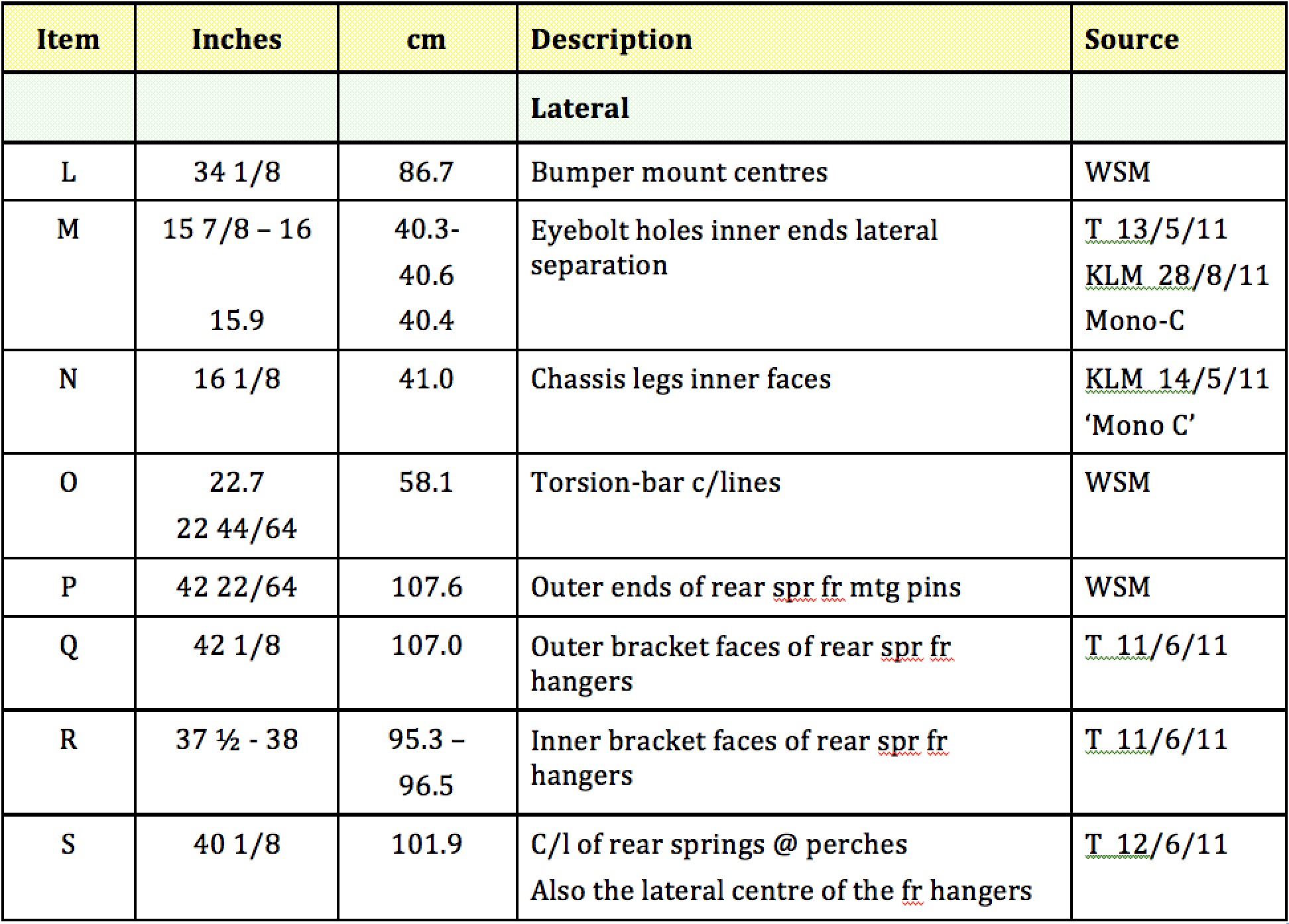
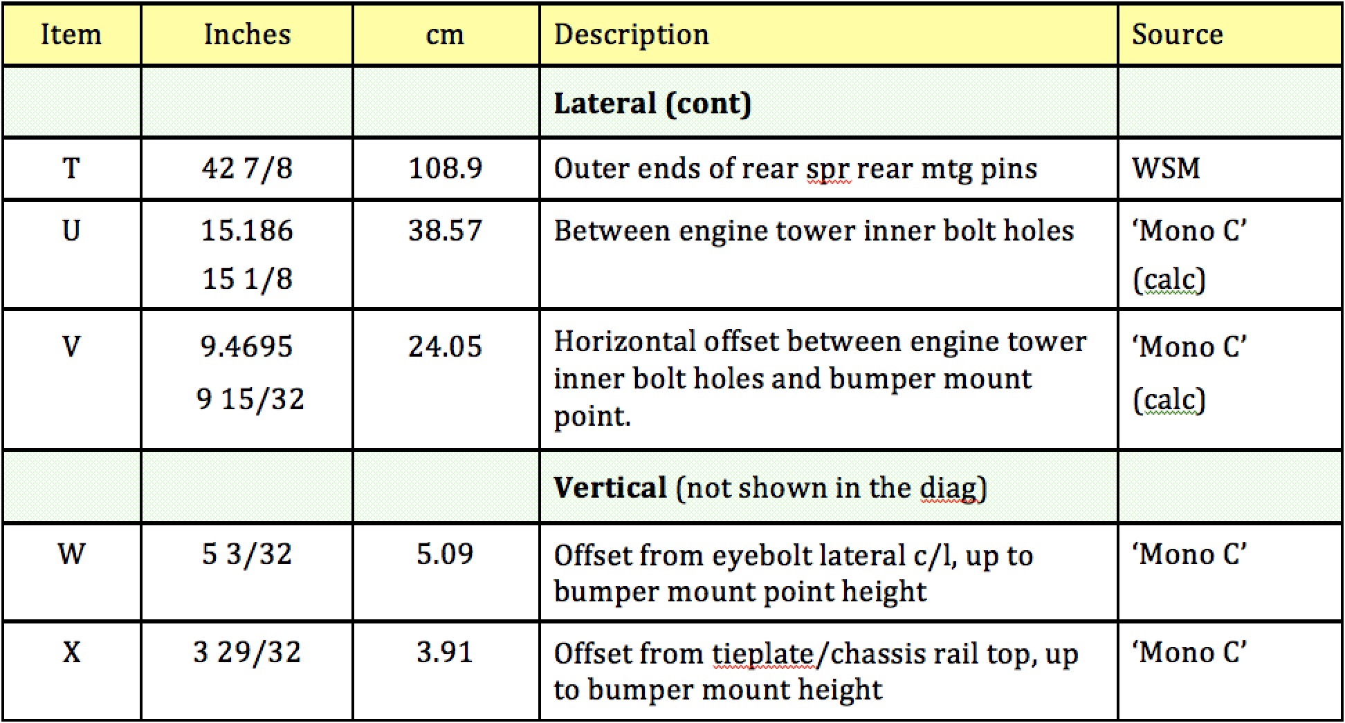
The alignment fixture drawing shows that the inner engine mounting holes as 7.593 x2 =15.186 = 15+3/16" apart. The outer mount holes are a further 3.375 out on each side so this makes them 21+15/16" apart. This should make the centres of the engine mount tower 18+9/16" apart and this being the distance between the centres of the legs but I do wonder if this is meant to be 18+5/8"?
The legs being 2+5/8" wide each this makes the "N" the distance between the insides of the chassis legs as 15+15/16" or more likely 16"if my above theory is right?
There are two holes in the reproduction crossmember that sit within the chassis legs (for the brake pipes?) and their centres are 18+5/8" which ties in with my above thoughts.
The Chassis Alignment fixture positions the legs apart on their inside faces 7.937 x 2 =15+7/8", I have read elsewhere that perhaps there should be a fitting clearance added here of 1/16" each side which would again make the legs 16" apart. So I ask if you think that the 16+1/8" you have for "N" is correct.
Also you have for "O" the torsion bar centres as 22+44/64" - that should be 22+11/16" but 58.1cm = 22+7/8" as near as dam it by the way but my reproduction crossmember measures 22+13/16".
Cheers
Martin
Re: Bodywork dimensions
Posted: Sun Apr 18, 2021 3:35 am
by don58van
Hello again Martin
I only this morning made the changes to my diagram and table resulting from your previous feedback. There has been a long delay, because I lost the files

A few days ago, I decided that I would try a different search strategy. Ultimately, it worked and I found the files.
Now I will have a look at your new observations to see if I made another mistake. Either way, I will have a revised table and diagram up soon.
I hope things are now falling into place (metaphorically speaking) with the fit of your car's bodywork.
Regards
Don